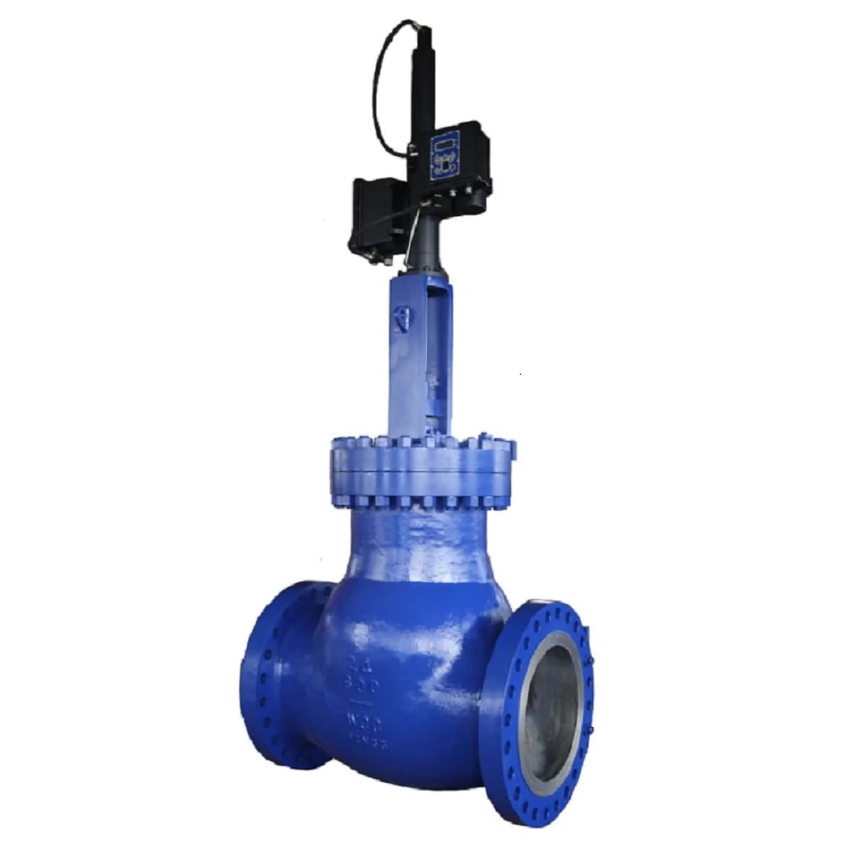
The electric hydraulic balanced control valve ensures precise flow regulation with balanced plug design for reduced actuator load, ideal for high-pressure oil, gas, and chemical systems up to pn40 and 450°c.
The electric hydraulic balanced control valve ensures precise flow regulation with balanced plug design for reduced actuator load, ideal for high-pressure oil, gas, and chemical systems up to pn40 and 450°c.
Reliable electro-hydraulic valve solution for water, oil, and gas pipelines.
An electric hydraulic control valve, also known as an electro-hydraulic valve, is a solenoid-operated directional valve. The solenoid coil generates a magnetic field to actuate the valve spool, allowing the flow of liquid to open, close, or change direction. This ensures precise control in hydraulic systems.
A control valve regulates flow, pressure, temperature, or other process variables. The choice of valve depends on pipe size, system pressure, media type, and operating conditions. By maintaining stability and safety, these valves ensure efficient operation of pipelines and equipment.
Fast, accurate actuation with solenoid and hydraulic power for precise flow control.
Suitable for water, oil, and gas pipelines with various industrial standards.
Designed to API and ASME standards with durable construction and long service life.
| Size | 2" and above |
|---|---|
| Pressure Rating | 150LB and higher |
| Design Temperature | ASME B16.34 pressure–temperature rating |
| Applications | Water, oil, gas |
| Design & Manufacture | API 600, API 6D, ASME B16.34 (others on request) |
| F to F Dimensions | API 6D, ASME B16.10, BS EN 558 |
| Connections | ASME B16.5, EN 1092, JIS 5K–20K; BW, RTJ available |
| Structure | Flexible or solid disc, OS&Y, BB, FB |
| Body & Bonnet | ASTM A216 WCB |
|---|---|
| Plug | ASTM A216 WCB + hard faced |
| Cage | ASTM A276 416 |
| Stem | ASTM A182 F6A, F304, F316, XM-19, 17-4PH, Inconel 718, Monel K-500 |
| Seat | ASTM A105 + hard faced |
| Operator | Electric hydraulic actuator (on/off or modulating type) |
*Special materials available upon request.
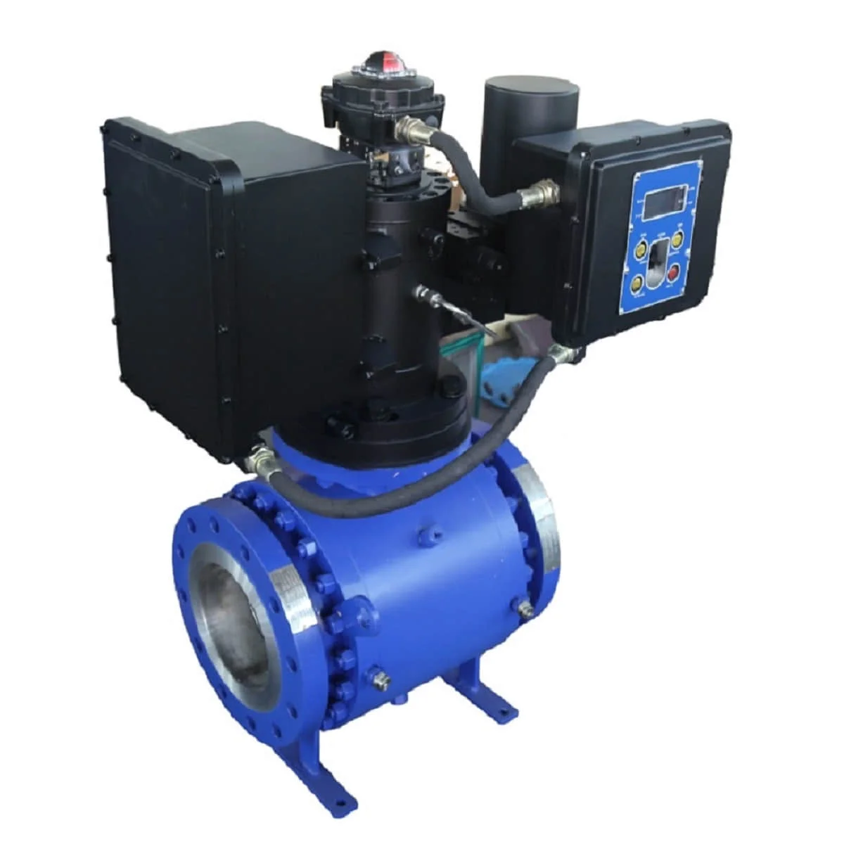
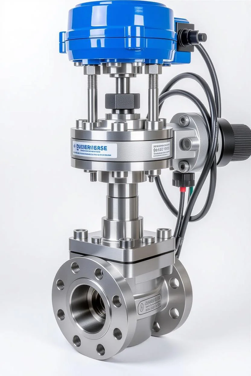
The Electric Hydraulic Balanced Control Valve is an advanced flow regulation device engineered for precise control in demanding industrial applications, featuring a balanced plug design that minimizes actuator thrust for efficient operation. This electro-hydraulic valve integrates electric actuation with hydraulic balancing to handle high-pressure differentials, ensuring stable performance in oil and gas, petrochemical, and power generation systems. Constructed from robust materials like ASTM A216 WCB carbon steel or CF8M stainless steel, with optional PTFE or metal seats, it offers superior corrosion resistance, making it ideal for industrial hydraulic valve duties in corrosive environments.
Operating via an electric actuator that modulates hydraulic fluid to the balanced plug, the balanced control valve provides equal percentage or linear flow characteristics for accurate throttling, supporting pressure ratings up to PN40 (ANSI Class 600) and temperatures from -29°C to 450°C. Compliant with IEC 60534 for control valve performance and ASME B16.34 for manufacturing, it features a cage-guided trim to reduce cavitation and noise, with Cv values up to 10,000 for versatile flow control. The balanced design equalizes pressure across the plug, reducing actuator size by up to 50% and enabling reliable operation in high-differential pressure scenarios, such as steam lines or gas pipelines.
The valve’s robust construction includes a pressure-balanced plug with upper and lower balancing holes, preventing unbalanced forces and ensuring smooth stem movement even under extreme loads. Its corrosion resistant valve properties are enhanced by hard-facing like Stellite on seats and discs, resisting erosion from abrasive media like slurries or corrosive gases, while optional bellows seals provide zero-emission compliance for hazardous applications. Electric actuators, compatible with 4-20mA, HART, or Foundation Fieldbus protocols, facilitate seamless integration into DCS or PLC systems, with feedback via linear variable differential transformers (LVDT) for position accuracy within ±1%. Rigorous testing per API 598, including hydrostatic shell tests and actuator response verification, confirms tensile strengths above 515 MPa, ensuring durability under cyclic loading.
Compared to unbalanced globe valves, the electric hydraulic control valve offers lower torque requirements and extended actuator life, ideal for automated processes requiring frequent modulation. Its modular trim allows for easy upgrades to anti-cavitation or low-noise configurations, reducing maintenance costs in precision flow valve applications. Optional hydraulic override enables manual emergency operation, while cryogenic extensions support LNG service down to -196°C. The valve’s ability to handle viscous fluids and high velocities without instability makes it a preferred choice for refinery fractionators or boiler controls.
Addressing challenges like actuator overload, flow instability, and fugitive emissions in industrial flow regulation, this balanced control valve incorporates double-packed stems and leak-off ports for enhanced safety. Its compatibility with global standards like API 609 for face-to-face dimensions ensures seamless integration into existing pipelines. Surface treatments such as 3LPE or FBE coatings further boost external protection against atmospheric corrosion. Whether throttling steam in power plants or regulating chemical flows in processing facilities, the Electric Hydraulic Balanced Control Valve delivers unmatched precision, reliability, and efficiency for engineers tackling complex hydraulic control needs.
Engineered for precise hydraulic flow control with balanced design and electric actuation.
Control valves are the most common final control elements in process control industries, manipulating fluid flow to maintain system stability and efficiency.
The control valve manipulates flowing media such as gas, steam, water, or chemicals to compensate for load disturbances and keep the process variable close to the desired set point.
Although they are vital for process performance, control valves are often overlooked due to the complexity of fluid mechanics, metallurgy, noise control, and piping design involved in demanding applications.
A control loop typically consists of a sensor, a transmitter, a controller, and the final control element. The valve acts as the “muscle” of the system, executing the corrective signals received from the controller.
In an automatic control system, sensors are the eyes, the controller is the brain, and the final control element—the valve—is the hands. While indispensable, it is sometimes the least understood part of the loop.
Control valves automatically regulate pressure and flow rate in process systems. They are essential final control elements in industrial automation, ensuring reliable performance and maintaining desired process conditions.
Control valves are available for any pressure class. For plants operating with pressure and temperature combinations that require Class 300 valves, all control valves may be selected as Class 300 for interchangeability. However, if system conditions do not exceed Class 150, higher ratings are not necessary.
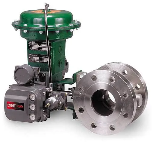
Globe valves are most commonly used for control applications, typically featuring flanged ends for easier maintenance. The valve disk is actuated by hydraulic, pneumatic, electrical, or mechanical systems, modulating flow by adjusting the position of a plug relative to the valve port.
In modern process plants, hundreds or thousands of control loops work together to maintain variables such as pressure, flow, level, and temperature. Each loop must stay within a defined range to ensure consistent product quality, while minimizing the effect of disturbances caused by system dynamics or interactions between loops.
To reduce disturbances, sensors and transmitters monitor process variables, feeding information to a controller. The controller calculates corrective actions, which are executed by the control valve, the final control element of the loop.
Maintains pressure and flow rate within safe operating limits to ensure process stability.
Globe valves are standard for control. Discs and plugs are precisely actuated to modulate flow effectively.
Works as the final control element, responding to controller signals to implement process corrections.
Flow control valves, also known as regulating valves, are essential components in fluid systems where precise control of flow rate is required.
A flow control valve adjusts the rate of fluid flow in a system. These valves are crucial in processes requiring stable and accurate control of liquid or gas flow, ensuring system efficiency and safety.
A pneumatic flow control valve combines a valve and an actuator, using compressed air to regulate flow. This design enables fast response times and high precision, making it ideal for automated systems.
Technically, a flow control valve regulates flow rate, which can indirectly influence pressure within a system. By restricting fluid movement, the valve creates a pressure drop upstream.
However, its primary function is flow management, not pressure reduction. If precise pressure regulation is required, specialized pressure-reducing valves should be considered alongside flow control valves.
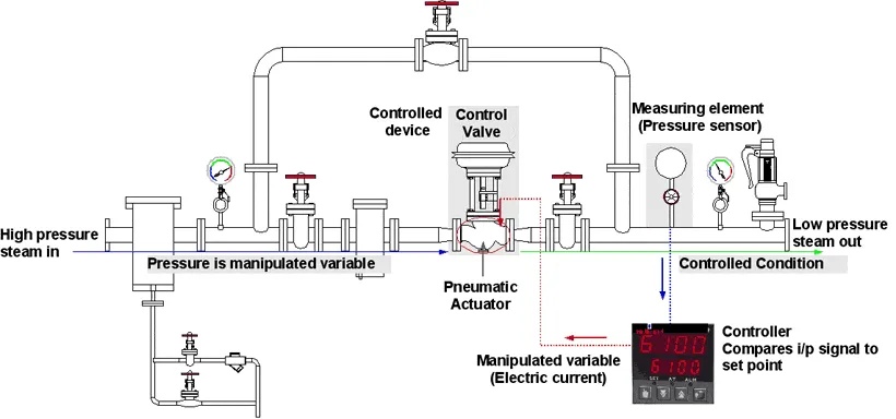
The diagram below illustrates how a control valve regulates the flow rate in a pipeline. The controller compares the actual flow with the desired setpoint and adjusts the valve accordingly. Similar arrangements are used for other variables like temperature, pressure, and liquid level.
Sensors measure process conditions such as flow, pressure, or temperature.
Receives input, compares with setpoint, and sends corrective signals to the valve.
Modulates flow by adjusting valve opening, ensuring stable operation.
Control valve arrangements are not limited to flow regulation. They can be applied to manage temperature, pressure, level, and flow rate — the most common controlled variables in industrial process systems.
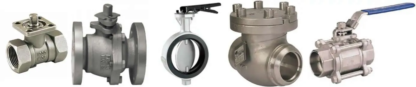
Different valves serve specific functions such as isolation, throttling, pressure relief, or directional change. The table below summarizes common valve types and their typical applications.
DC = Directional Change
IoS = Isolation or Stop
PR = Pressure Relief
TH = Throttling
| Valve Type | IoS | TH | PR | DC |
|---|---|---|---|---|
| Gate | YES | NO | NO | NO |
| Globe | YES | YES | NO | YES (1) |
| Check | (2) | NO | NO | NO |
| Stop Check | YES | NO | NO | NO |
| Butterfly | YES | YES | NO | NO |
| Ball | YES | (3) | NO | YES (4) |
| Plug | YES | (3) | NO | YES (4) |
| Diaphragm | YES | NO | NO | NO |
| Safety Relief | NO | NO | YES | NO |
Notes:
| Organization | Standard | Description |
|---|---|---|
| ANSI | American National Standards Institute | General industrial standards |
| API | American Petroleum Institute | Standards for oil and gas industry |
| ASME | American Society of Mechanical Engineers | Boiler and pressure vessel codes |
| BS | British Standards | UK national standards |
| GB, JB, HG | China Valve Standards | Chinese national and industry standards |
Upstream, midstream, and downstream operations, including drilling, refining, and transportation.
Handling corrosive and hazardous chemicals in various chemical plants.
Steam, water, and fuel systems in thermal, nuclear, and hydroelectric plants.
Municipal water supply, wastewater treatment, and industrial water management.
Heating, ventilation, and air conditioning systems in commercial and industrial buildings.
Sterile and hygienic applications, precise flow control in sensitive industries.