- Robust Design For Accurate Flow Control In Industrial Pipelines
The control valve provides precise flow regulation with corrosion-resistant materials for water, oil, gas, and chemical systems, ensuring reliable performance up to pn40 and 450°c.
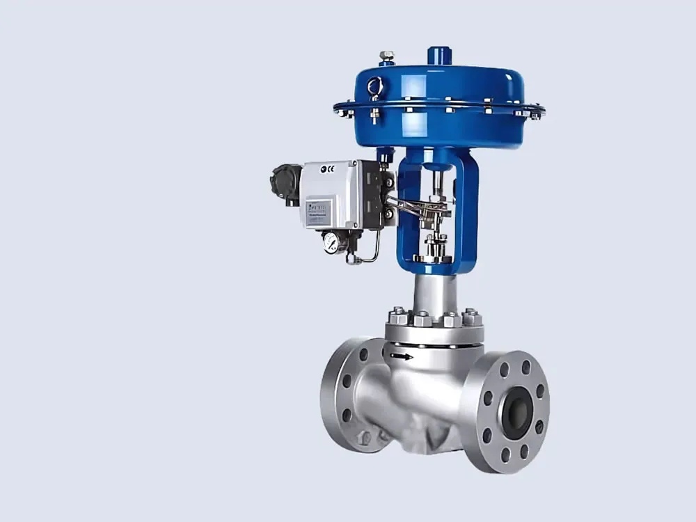
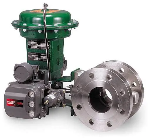
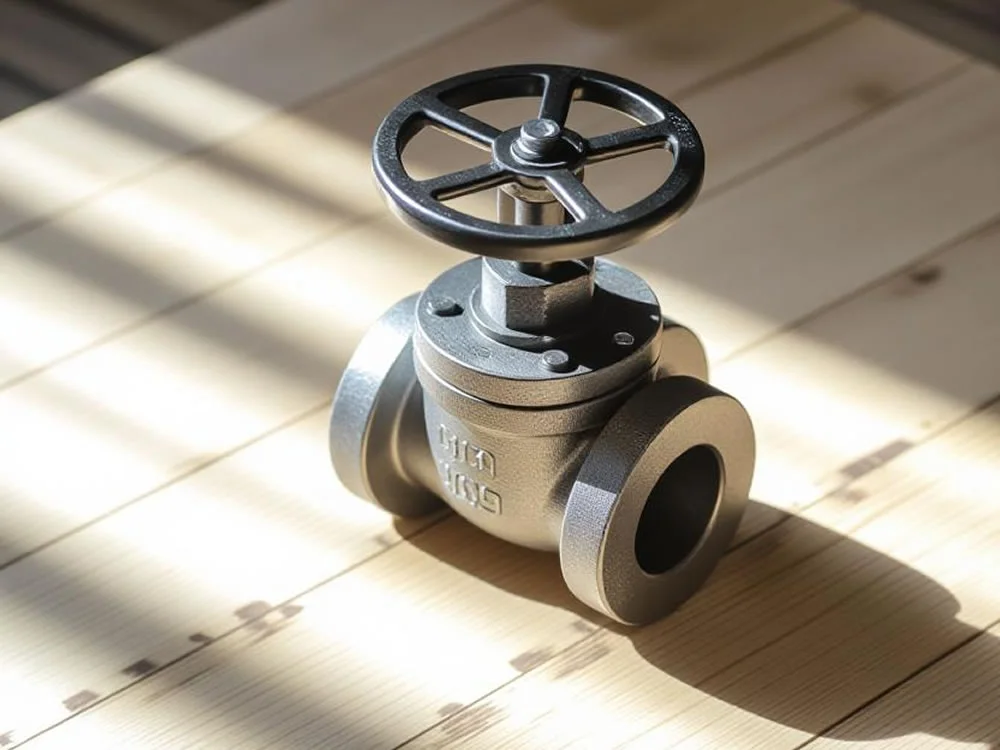
The Control Valve is a precision-engineered valve designed for accurate flow regulation in industrial pipelines, offering reliable throttling and shutoff for water, oil, gas, and chemical systems. Utilizing a globe, butterfly, or ball valve configuration with advanced actuators (pneumatic, electric, or hydraulic), it ensures precise control of flow rate, pressure, and temperature. Constructed from materials like ASTM A216 WCB carbon steel, ASTM A351 CF8M stainless steel, or alloy steels, with optional coatings such as PTFE or epoxy, it provides exceptional corrosion resistance, making it ideal for industrial flow regulation in oil and gas, petrochemical, power generation, and water treatment industries.
Compliant with ASME B16.34 for manufacturing and API 609 or IEC 60534 for design and performance, the control valve is available in sizes from 1/2" to 24" (DN15 to DN600) with flanged, threaded, or butt-weld end connections per ASME B16.5 and B16.25. It supports pressure ratings up to PN40 (ANSI Class 150-600) and temperatures from -29°C to 450°C, depending on seat materials like PTFE for low temperatures or metal-to-metal for high-temperature applications. The valve’s trim, designed with equal percentage, linear, or quick-opening flow characteristics, allows precise modulation with Cv values up to 12,000, optimizing flow control valve performance. Certifications such as SIL 3 per IEC 61508 and NACE MR0175 for sour service ensure reliability in critical applications.
The valve’s robust construction features a forged or cast body with a balanced plug or cage-guided trim, reducing cavitation and noise in high-pressure differential systems. Its corrosion resistant valve properties are enhanced by coatings and linings that protect against aggressive media like acids, seawater, or slurries, extending service life up to three times longer than uncoated valves in corrosive environments. Actuation systems, compatible with 4-20mA or digital protocols like HART or Foundation Fieldbus, enable precise automation in SCADA-integrated systems. Rigorous testing per API 598, including hydrostatic, pneumatic, and leakage tests, confirms tensile strengths above 485 MPa, ensuring durability under cyclic loading and thermal stress.
Compared to gate or check valves, the control valve offers superior throttling precision, with flow accuracy within ±2% of setpoint, making it ideal for processes requiring tight control, such as boiler feedwater regulation or gas pressure management. Its modular design allows for easy trim replacement and maintenance, reducing downtime in precision control valve applications. Optional features like anti-cavitation cages, low-noise trims, or bellows seals for zero-emission compliance enhance versatility for chemical plants, HVAC systems, and marine applications. The valve’s ability to handle high-viscosity fluids and abrasive slurries ensures consistent performance in demanding conditions.
Addressing challenges like flow instability, pipeline corrosion, and fugitive emissions, the control valve incorporates advanced packing systems and durable seals to ensure long-term integrity. Its compatibility with global flange standards (ANSI, DIN, JIS) and coatings like 3LPE or FBE ensures applicability in diverse environments, from buried pipelines to offshore platforms. Whether regulating flow in refinery processes or maintaining pressure in water distribution systems, the Control Valve delivers reliable, low-maintenance industrial flow regulation for global industrial operations.
Engineered for precise flow regulation with durable materials and advanced automation.
Control valves are the most common final control elements in process control industries, manipulating fluid flow to maintain system stability and efficiency.
The control valve manipulates flowing media such as gas, steam, water, or chemicals to compensate for load disturbances and keep the process variable close to the desired set point.
Although they are vital for process performance, control valves are often overlooked due to the complexity of fluid mechanics, metallurgy, noise control, and piping design involved in demanding applications.
A control loop typically consists of a sensor, a transmitter, a controller, and the final control element. The valve acts as the “muscle” of the system, executing the corrective signals received from the controller.
In an automatic control system, sensors are the eyes, the controller is the brain, and the final control element—the valve—is the hands. While indispensable, it is sometimes the least understood part of the loop.
Control valves automatically regulate pressure and flow rate in process systems. They are essential final control elements in industrial automation, ensuring reliable performance and maintaining desired process conditions.
Control valves are available for any pressure class. For plants operating with pressure and temperature combinations that require Class 300 valves, all control valves may be selected as Class 300 for interchangeability. However, if system conditions do not exceed Class 150, higher ratings are not necessary.
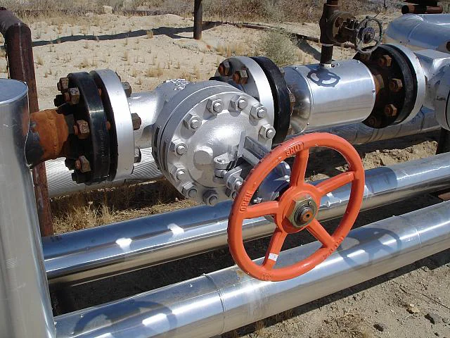
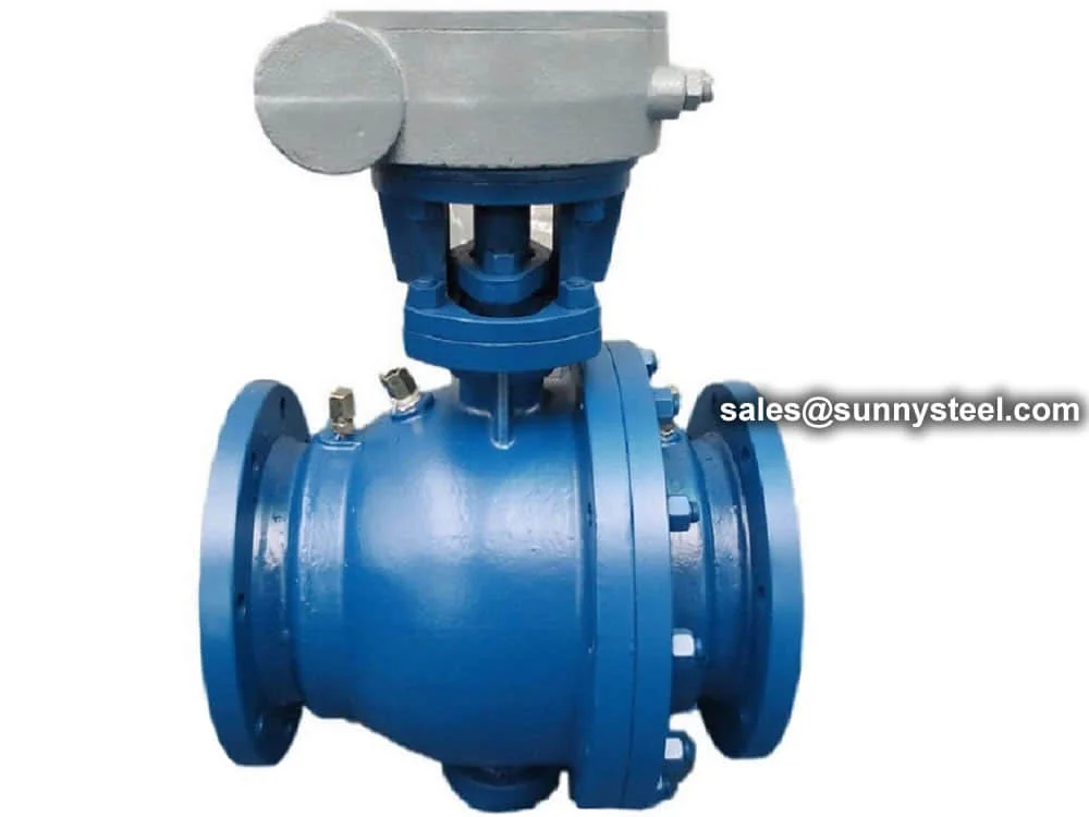
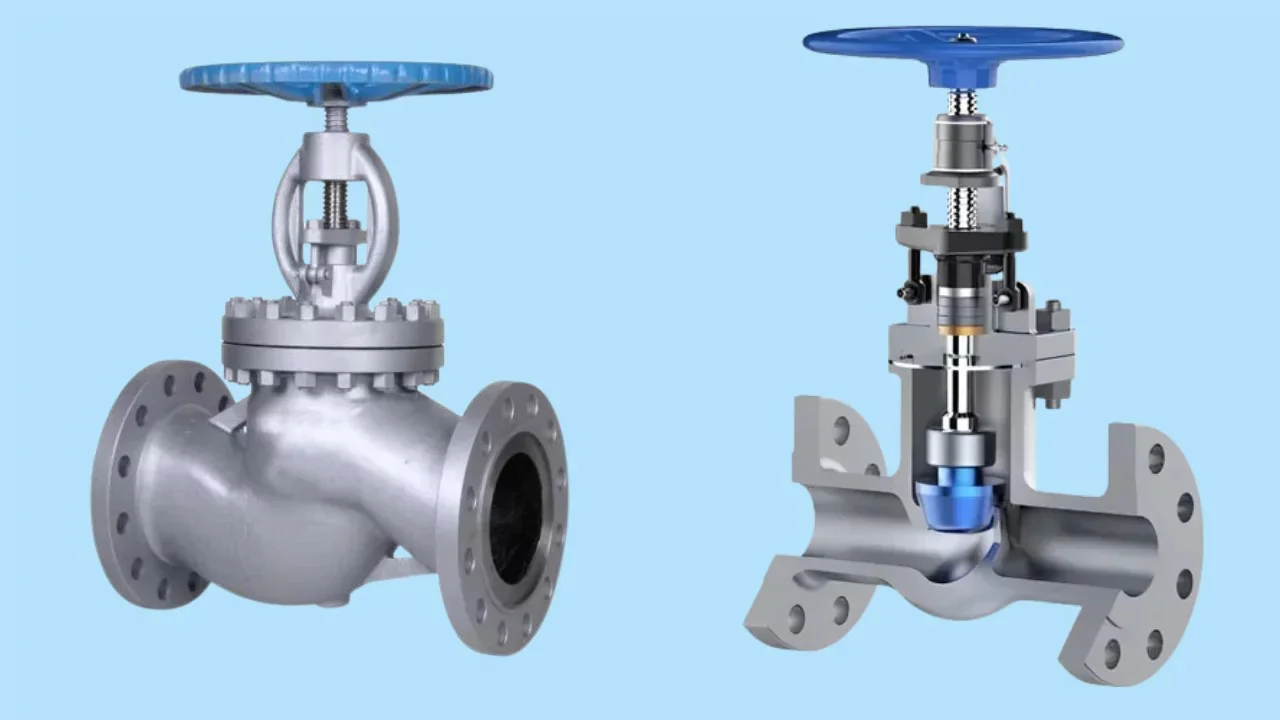
Globe valves are most commonly used for control applications, typically featuring flanged ends for easier maintenance. The valve disk is actuated by hydraulic, pneumatic, electrical, or mechanical systems, modulating flow by adjusting the position of a plug relative to the valve port.
In modern process plants, hundreds or thousands of control loops work together to maintain variables such as pressure, flow, level, and temperature. Each loop must stay within a defined range to ensure consistent product quality, while minimizing the effect of disturbances caused by system dynamics or interactions between loops.
To reduce disturbances, sensors and transmitters monitor process variables, feeding information to a controller. The controller calculates corrective actions, which are executed by the control valve, the final control element of the loop.
Maintains pressure and flow rate within safe operating limits to ensure process stability.
Globe valves are standard for control. Discs and plugs are precisely actuated to modulate flow effectively.
Works as the final control element, responding to controller signals to implement process corrections.
Flow control valves, also known as regulating valves, are essential components in fluid systems where precise control of flow rate is required.
A flow control valve adjusts the rate of fluid flow in a system. These valves are crucial in processes requiring stable and accurate control of liquid or gas flow, ensuring system efficiency and safety.
A pneumatic flow control valve combines a valve and an actuator, using compressed air to regulate flow. This design enables fast response times and high precision, making it ideal for automated systems.
Technically, a flow control valve regulates flow rate, which can indirectly influence pressure within a system. By restricting fluid movement, the valve creates a pressure drop upstream.
However, its primary function is flow management, not pressure reduction. If precise pressure regulation is required, specialized pressure-reducing valves should be considered alongside flow control valves.
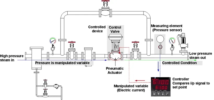
The diagram below illustrates how a control valve regulates the flow rate in a pipeline. The controller compares the actual flow with the desired setpoint and adjusts the valve accordingly. Similar arrangements are used for other variables like temperature, pressure, and liquid level.
Sensors measure process conditions such as flow, pressure, or temperature.
Receives input, compares with setpoint, and sends corrective signals to the valve.
Modulates flow by adjusting valve opening, ensuring stable operation.
Control valve arrangements are not limited to flow regulation. They can be applied to manage temperature, pressure, level, and flow rate — the most common controlled variables in industrial process systems.
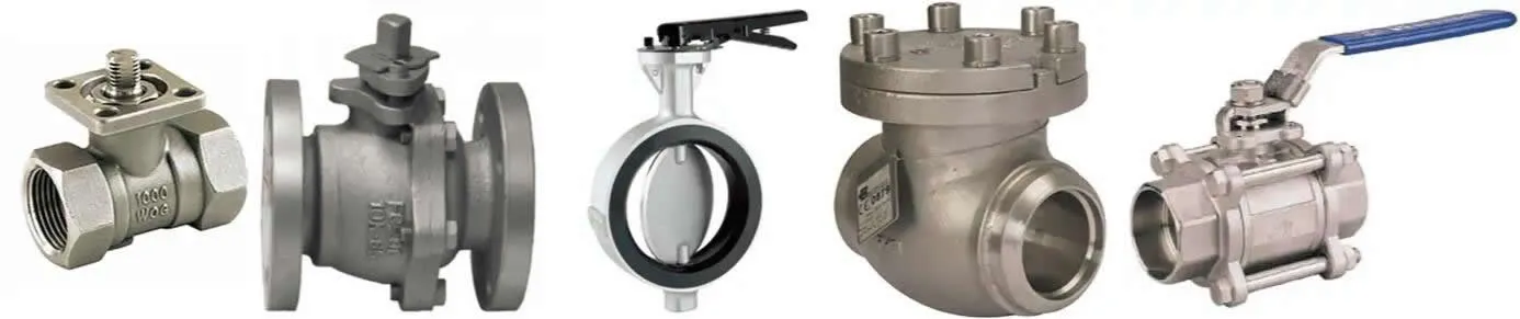
Different valves serve specific functions such as isolation, throttling, pressure relief, or directional change. The table below summarizes common valve types and their typical applications.
DC = Directional Change
IoS = Isolation or Stop
PR = Pressure Relief
TH = Throttling
| Valve Type | IoS | TH | PR | DC |
|---|---|---|---|---|
| Gate | YES | NO | NO | NO |
| Globe | YES | YES | NO | YES (1) |
| Check | (2) | NO | NO | NO |
| Stop Check | YES | NO | NO | NO |
| Butterfly | YES | YES | NO | NO |
| Ball | YES | (3) | NO | YES (4) |
| Plug | YES | (3) | NO | YES (4) |
| Diaphragm | YES | NO | NO | NO |
| Safety Relief | NO | NO | YES | NO |
Notes:

Comprehensive list of key international valve standards from major organizations, updated as of 2025.
| Organization | Standard | Description |
|---|---|---|
| ANSI | American National Standards Institute | General industrial standards |
| API | American Petroleum Institute | Standards for oil and gas industry |
| ASME | American Society of Mechanical Engineers | Boiler and pressure vessel codes |
| BS | British Standards | UK national standards |
| GB, JB, HG | China Valve Standards | Chinese national and industry standards |
| FCI | Fluid Control Institute | Standards for fluid control and conditioning equipment |
American National Standards Institute
| Code | ANSI Standard Name |
|---|---|
| ANSI A126 | Grey Iron Castings for Valves, Flanges, and Pipe Fittings |
| ANSI A181 | Forged or Rolled Steel Pipe Flanges, Forged Fittings, and Valves and Parts for General Service |
| ANSI B16.10 | Face-to-Face and End-to-End Dimensions of Valves |
| ANSI B16.34 | Valves - Flanged, Threaded, and Welding End |
| ANSI B16.5 | Pipe Flanges and Flanged Fittings |
| ANSI/FCI 70-2 | Control Valve Seat Leakage |
| ANSI B127.1 | Constant-Level Oilers |
American Petroleum Institute
| Code | API Standard Name |
|---|---|
| API 526 | Flanged Steel Pressure-Relief Valves |
| API 527 | Seat Tightness of Pressure Relief Valves |
| API 594 | Check Valves: Flanged, Lug, Bolted Bonnet |
| API 595 | Cast Iron Gate Valves - Flanged Bonnet |
| API 597 | Steel Venturi Gate Valves - Flanged and Welding Ends |
| API 598 | Valve Inspection and Testing |
| API 599 | Steel and Ductile Iron Plug Valves |
| API 600 | Bolted Bonnet Steel Gate Valves for Refinery Service |
| API 602 | Compact Steel Gate Valves - Flanged, Threaded, and Welding Ends |
| API 603 | Corrosion-Resistant Gate Valves - Flanged Ends |
| API 604 | Ductile Iron Gate Valves - Flanged Ends |
| API 607 | Fire Test for Quarter-Turn Valves |
| API 608 | Metal Ball Valves - Flanged, Threaded, and Welding Ends |
| API 609 | Butterfly Valves: Double Flanged, Lug- and Wafer-Type |
| API 6D | Pipeline and Piping Valves |
| API 6FA | Fire Test for Valves |
| API RP 574 | Inspection Practices for Piping System Components |
| API RP 576 | Inspection of Pressure-Relieving Devices |
American Society of Mechanical Engineers
| Code | ASME Standard Name |
|---|---|
| ASME A105/A105M | Carbon Steel Forgings for Piping Applications |
| ASME A181/A181M | Carbon Steel Forgings, for General-Purpose Pipes |
| ASME A182/A182M | Forged or Rolled Alloy and Stainless Steel Pipe Flanges, Forged Fittings, and Valves and Parts for High-Temperature Service |
| ASME A350/A350M | Carbon and Low-Alloy Steel Forgings for Low-Temperature Service |
| ASME A694/A694M | Carbon and Alloy Steel Forgings for Pipe Flanges, Fittings, Valves, and Parts for High-Pressure Transmission Service |
| ASME B16.5 | Pipe Flanges and Flanged Fittings: NPS 1/2 Through NPS 24 Metric/Inch Standard |
| ASME B16.10 | Face-to-Face and End-to-End Dimensions of Valves |
| ASME B16.11 | Forged Fittings, Socket-Welding and Threaded |
| ASME B16.34 | Valves - Flanged, Threaded, and Welding End |
| ASME B31.1 | Power Piping |
| ASME B31.3 | Process Piping |
| ASME F1508 | Standard Specification for Angle Style, Pressure Relief Valves for Steam, Gas, and Liquid Services |
| ASME F1565 | Pressure-Reducing Valves for Steam Service |
British Standards Institution
| Code | British Standard Name |
|---|---|
| BS 1212 | Float Operated Valves - Automatic Valves (Including Float Valves) for Tanks, Cisterns, Hot-Water Cylinders and Feed Cisterns |
| BS 1414 | Specification for Steel Wedge Gate Valves (Flanged and Butt-Welding Ends) for the Petroleum, Petrochemical and Allied Industries |
| BS 1552 | Specification for Control Plug Cocks for Low Pressure Gases |
| BS 1868 | Specification for Steel Check Valves (Flanged and Butt-Welding Ends) for the Petroleum, Petrochemical and Allied Industries |
| BS 1873 | Specification for Steel Globe and Globe Stop and Check Valves (Flanged and Butt-Welding Ends) for the Petroleum, Petrochemical and Allied Industries |
| BS 1952 | Specification for Copper Alloy Gate Valves for General Purposes |
| BS 2080 | Specification for Face-to-Face, Centre-to-Face, End-to-End and Centre-to-End Dimensions for Flanged and Butt-Welding End Steel Valves for the Petroleum, Petrochemical and Allied Industries |
| BS 2995 | Specification for Cast and Forged Steel Wedge Gate, Globe, Check and Plug Valves Screwed and Socket-Welding Sizes 1/2 in and Smaller for the Petroleum Industry |
| BS 3464 | Specification for Cast Iron Gate Valves for General Purposes |
| BS 5150 | Specification for Cast Iron Wedge and Double Disk Gate Valves for General Purposes |
| BS 5151 | Specification for Cast Iron Gate (Parallel Slide) Valves for General Purposes |
| BS 5152 | Specification for Cast Iron Globe and Globe Stop and Check Valves for General Purposes |
| BS 5153 | Specification for Cast Iron Check Valves for General Purposes |
| BS 5154 | Specification for Copper Alloy Globe, Globe Stop and Check, Check and Gate Valves for General Purposes |
| BS 5155 | Specification for Butterfly Valves for General Purposes |
| BS 5156 | Specification for Screw-Down Diaphragm Valves for General Purposes |
| BS 5157 | Specification for Steel Gate (Parallel Slide) Valves for General Purposes |
| BS 5159 | Specification for Cast Iron and Carbon Steel Ball Valves for General Purposes |
| BS 5160 | Specification for Steel Globe Valves, Globe Stop Valves, Stop and Check Valves and Lift Type Check Valves |
| BS 5351 | Specification for Steel Ball Valves for Petroleum, Petrochemical and Allied Industries |
| BS EN 12266-1 | Industrial Valves - Testing of Metallic Valves Part 1: Pressure Tests - Test Procedures |
China National Standards
| Code | GB Standard Name | Adopting Standard |
|---|---|---|
| GB 12220 | General Valve - Marking | ISO 5209 |
| GB 12221 | Flanged Ends Metal Valve - Face-to-Face Dimensions | ISO 5752 |
| GB 12222 | Multi-Turn Valve - The Connection of the Driving Device | ISO 5210/1-3 |
| GB 12223 | Part-Turn Valve - The Connection of the Driving Device | ISO 5211/1-3 |
| GB 12224 | Steel Valve - General Requirements | ANSI B16.34 |
| GB 12225 | General Valve - Copper Alloy Casting Ware Technology Requirements | ASTM B584 |
| GB 12226 | General Valve - Gray Cast Iron Technology Requirements | ISO 185, BS 1452 |
| GB 12228 | General Valve - Carbon Forging Steel Technology Requirements | ASTM A105, A181 |
| GB 12229 | General Valve - Carbon Casting Steel Technology Requirements | ASTM A703 |
| GB 12230 | General Valve - Austenitic Casting Steel Technology Requirements | ASTM A351 |
| GB 12232 | General Valve - Flanged Ends Iron Gate Valve | ISO 5996-1982, API 595 |
| GB 12233 | General Valve - Iron Gate Valve and Lift Check Valve | BS 5152, 5153 |
| GB 12234 | General Valve - Flanged and Butt-Welding Ends Copper Gate Valve | API 600 |
| GB 12237 | General Valve - Flanged and Butt-Welding Ends Steel Ball Valve | ISO 7121, API 607 |
| GB 12238 | General Valve - Flanged and Wafer Ends Butterfly Valve | BS 5155 |
| GB 12239 | General Valve - Diaphragm Valve | BS 5156, NFE 29 |
| GB 12240 | General Valve - Iron Plug Valve | API 593 |
| GB 12241 | Safety Valve - General Requirements | ISO 4126 |
| GB 12242 | Safety Valve - Characteristic Testing Solution | ANSI/ASME PTC 25.3 |
| GB 12243 | Direct Spring-Loaded Safety Valve | JIS B 8210 |
| GB 12244 | Pressure Reducing Valve - General Requirements | JIS B 8372, B8410 |
| GB 12245 | Pressure Reducing Valve - Characteristic Testing Solution | JIS B 8372, B8410 |
| GB 12246 | Pilot Operated Pressure Reducing Valve | JIS B 8372, DSS 405 |
| GB 12247 | Steam Trap Valve - Classification | ISO 6704 |
| GB 12248 | Steam Trap Valve - Technology Terms | ISO 6552 |
| GB 12249 | Steam Trap Valve - Marking | ISO 6553 |
| GB 12250 | Steam Trap Valve - Face-to-Face Dimensions | ISO 6554 |
| GB 12251 | Steam Trap Valve - Testing Solution | ISO 6948, 7841, 7842 |
| GB/T 13927 | General Valve - Pressure Testing | ISO 5208 |
| JB/T 6899-93 | Valve Fire-Proof Test | ISO 10497 |
| JB/T 7927-95 | Valve Casting Steelware Out-Form Quality Requirements | MSS SP-55 |
| ZBJ 16006-90 | Inspection and Testing of Valve | API 598 |
| Code | GB Standard Name |
|---|---|
| GB 12227 | General Valve - Ductile Cast Iron Technology Requirements |
| GB 12235 | General Valve - Flanged Steel Stop and Lift Check Valve |
| GB 12236 | General Valve - Steel Swing Check Valve |
| GB/T 13932 | General Valve - Iron Swing Check Valve |
| GB/T 15185 | Iron and Copper Ball Valve |
| GB/T 15188.1 | Valve Face-to-Face Dimensions - Butt-Welding Ends Valve |
| GB/T 15188.2 | Valve Face-to-Face Dimensions - Wafer Ends Valve |
| GB/T 15188.3 | Valve Face-to-Face Dimensions - Female Screw-Down Valve |
| GB/T 15188.4 | Valve Face-to-Face Dimensions - Male Screw-Down Valve |
| JB 93 | Handle |
| JB/T 450 | PN16-32.0 MPa Forging Angle Type High-Pressure Valve, Fastener, and Technology Requirements |
| JB/T 7745-95 | Pipeline Ball Valve |
| JB/T 8527-97 | Metal Sealing Butterfly Valve |
| JB/T 8473-96 | Instrument Valve Series |
| ZBJ 16004-88 | Reducing Valve Type and Basing Coefficient |
| ZBJ 16007-90 | Steam Trap Valve Technology Terms |
| ZBJ 16009-90 | Valve Pneumatic Actuator Technology Terms |
Standards for fluid control and conditioning equipment
The Fluid Control Institute (FCI) provides standards to assist in understanding and using control valves, solenoid valves, and regulators.
| Code | FCI Standard Name |
|---|---|
| ANSI/FCI 70-2 | Control Valve Seat Leakage |
| ANSI/FCI 70-3 | Control Valve Aerodynamic Noise Prediction |
| ANSI/FCI 91-1 | Qualification of Control Valve Stem Seals |
| ANSI/FCI 85-1 | Method of Determining the Thermal Expansion of a Filled Thermal System |
| FCI 68-2 | Procedure in Rating Flow and Pressure Characteristics of Solenoid Valves for Liquid Service |
| FCI 75-1 | Test Conditions and Procedures for Measuring Electrical Characteristics of Solenoid Valves |
| FCI 82-1 | Recommended Methods for Testing and Classifying the Water Hammer Characteristics of Electrically Operated Valves |
| ANSI/FCI 69-1 | Pressure Ratings of Traps |
Upstream, midstream, and downstream operations, including drilling, refining, and transportation.
Handling corrosive and hazardous chemicals in various chemical plants.
Steam, water, and fuel systems in thermal, nuclear, and hydroelectric plants.
Municipal water supply, wastewater treatment, and industrial water management.
Heating, ventilation, and air conditioning systems in commercial and industrial buildings.
Sterile and hygienic applications, precise flow control in sensitive industries.
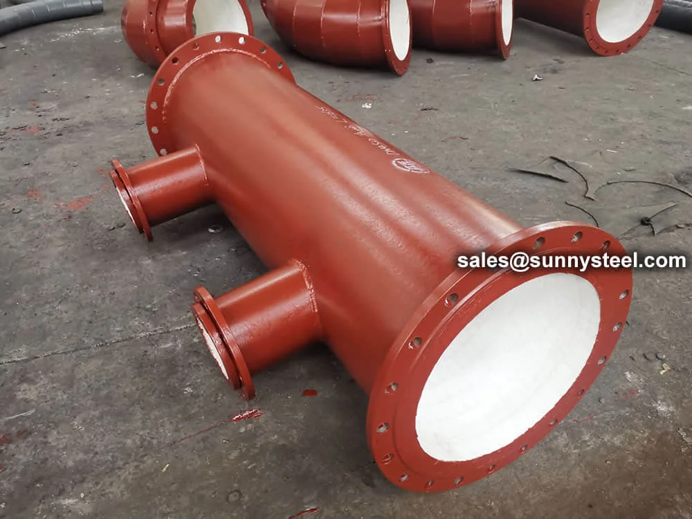
Customized Alumina Ceramic Lined Project
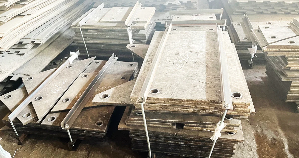
Wear-Resistant Hardfacing Liner Plate